Learn more about low shear

Learn more about low shear

Droplet break-up in valves

Introduction

It is a well-established fact that shear forces in valves cause droplet break-up and emulsification in multiphase flows. The shearing of droplets in high intensity turbulent areas within the valve causes oil droplets to deform and break. The results of emulsification and droplet break-up of the dispersed phase is reduced efficiency in downstream separation equipment.

This series of articles will look at how droplet shearing in valves affects the downstream droplet size and separation efficiency. Effect of valve trim and other solutions to reduce the harm of valve shearing on downstream separation equipment will be presented, backed up with field and test data.

Droplet Formation

The two phenomena governing the droplet size in a multiphase flow are droplet breakup and droplet-droplet coalescence. To what extent one of these phenomena is dominating, is affected by both fluid characteristics and the hydrodynamics. Fluid characteristics involve factors such as the oil concentration, droplet size distribution, oil and water density, oil and water viscosity, water temperature and salinity, and surfactants. Hydrodynamics are related to the flow regimes the droplets encounter and the forces exerted by these. For oil and gas production, the flow is turbulent and the droplet size is therefore a function of the intensity of the turbulence.

Droplet Break-up Theory

The mechanism of droplet breakup is typically expressed as a balance between the external stresses from the continuous phase and the surface stress of the droplet, plus the viscous stress of the fluid inside the droplet. The external stresses may destroy the droplet, while the surface stress and viscous stress restore the droplet's form. The balance of these stresses leads to a maximum stable droplet diameter, dmax. For droplets larger than dmax, the external stress overcome the restorative stresses, and the droplet breaks.

This balance of forces has been expressed mathematically by for example Hinze [1] where maximum droplet size that can survive a certain turbulent flow regime is given as:
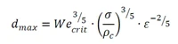
formel 2


Where:
Wecrit       Critical Weber number [-]
σ             Interfacial tension [N/m]
ρc           Density continuous phase [kg/m³]
ε             Mean energy dissipation rate per unit mass [W/kg]
 
The critical Weber number, the density, and the interfacial tension are all solely dependent on the fluid properties and composition. The mean energy dissipation rate per unit mass is therefore often regarded as the single measure of the turbulence intensity, allowing this factor to be used to evaluate the magnitude of droplet break-up or emulsification in a multiphase mixture.
 
For fluid flow through a valve or orifice, the mean energy dissipation rate per unit mass can be expressed as [2,3]:
formel 3


Where:
ΔPperm     The permanent pressure drop [Pa]
Q             Flow rate [m³/s]
Vdis          Volume used for energy dissipation [m³]

According to this equation, ε is directly proportional to 1/Vdis for constant process conditions and fluid compositions. Increasing the volume engaged in energy dissipation will, therefore, result in a decrease in ε, increasing the maximum droplet size that can tolerate the flow regime in the valve.
 

Effect of Inlet Droplet Size

As discussed, the maximum droplet that can survive the turbulent flow regime in a valve is directly related to the energy dissipation rate. For constant fluid properties and process conditions, the maximum droplet size that can be sustained by the turbulent flow regime, dmax is only dependent on the orifice or valve design. As a result, inlet droplets larger than dmax, will be reduced to dmax, which is clearly shown in Figure 1. This figure shows measurements of the Dv50 droplet size upstream and downstream of a valve, where the fluid composition and process conditions are kept constant and the only varying parameter is the inlet droplet size distribution.
1-2%202
Figure 1: Online measurements of Dv50 upstream and downstream a valve. (Click to enlarge figure)
In the figure, the red lines show the Dv50 at the inlet of the valve and the blue lines show Dv50 at the outlet of the valve. As expected from the theory, it is clearly seen that the outlet droplet size is not affected by the inlet droplet size distribution; at least as long as the inlet droplets are larger than dmax. Another way to show this is by looking at the droplet size distributions from the same test, as shown in Figure 2. Here it is seen that the outlet distributions are the same, regardless of the inlet distribution. The one exception is the purple distribution, which is already smaller than dmax and therefore not significantly affected by the turbulence in the valve.
2-2
Figure 2: Online measurements of droplet size distribution upstream and downstream a valve. (Click to enlarge figure)

Development of Bimodal Distributions

The energy dissipation rate is not homogeneously distributed in a valve. There will always be pockets of high intensity turbulence and high energy dissipation rates, and pockets with lower intensity turbulence. Not all droplets will pass through the same areas, and will therefore not experience the same shearing effect. This can cause what is known as bimodal droplet size distributions. Bimodal distributions show two or more tops in the droplet size distribution, and generally has a higher concentration of small droplets, i.e., the tail end of the distribution. This phenomenon becomes more prominent at increasing differential pressure, as shown in Figure 3. This graph shows the outlet droplet size distributions for a conventional valve for different pressure drops, with constant inlet droplet size and fluid properties. The results show a distinct increase in the tail end of the droplet size distribution, containing the smallest droplets.
2-4
Figure 3: Outlet droplet size distributions from a conventional valve at different pressure drops

Effect of Valve Trim

Conventional choke and control valves typically consist of a cage to give the valve the required characteristic (e.g. linear, equal percentage, fast opening) and a plug to control the flow area through the cage. The cage can have different designs based on the requirements for the choke or control valve, but can generally be divided into two types: Single stage cages and multistage cages. A single stage cage has orifices, e.g. holes or slots, straight through the cage. A multistage cage has a design where the fluids need to follow a winding channel through the cage and is therefore often called a labyrinth cage.

Single stage cages have an area directly behind the cage where there is high intensity turbulence, where most of the energy is dissipated. For this cage type, it is this volume behind the cage that determines the value for ε. For labyrinth cages however, the majority of the energy is dissipated inside the labyrinth channels in the cage wall. The volume involved in the energy dissipation for these types of cages is therefore very limited. This results in a higher ε, and therefore higher shear forces compared to that of a single stage cage. This analysis is confirmed by test data; an example of which is shown in Figure 4 where the droplet size distribution downstream a single stage and a labyrinth stage cage are compared.
2-3
Figure 4: Droplet size distribution for valves with a single stage cage and with a labyrinth type cage
The next article will focus on measures to reduce shear in valves and the positive effects this can have on the separation efficiency of downstream equipment.

Measures to Reduce Shear

According to equation 2, there are several ways to reduce shearing of droplets. Reducing the differential pressure over the valve will reduce ε, thereby increasing the maximum droplet size that can survive the turbulence flow regime in the valve. Though this is a method to reduce shear forces, in reality the possible reduction in differential pressure is generally limited. Doubling the outlet droplet size means that the energy dissipation rate has to be reduced with a factor 5 to 6, as can be seen from equation 1. Because of this, only a limited reduction of shear can be obtained by reducing the pressure drop. It is also equally impractical to reduce the flow rate or increase the density.

This leaves the volume involved in the energy dissipation as the only potential and practical method to reduce shearing.

Typhonix has developed a low shear valve trim in close cooperation with Mokveld Valves. This trim utilizes cyclonic flow to enable a large volume to be engaged in the energy dissipation. The low shear trim is implemented in the Typhoon Valve System®. The turbulence is less intense and more homogenous than for the other valve trims as can be seen in Figure 5.
 
fig%203-1
Figure 5: Outlet droplet size comparison between a standard (single stage) valve trim, a labyrinth valve trim and a Typhoon valve trim.
Using the Typhoon Valve System typically doubles the median droplet size (Dv50) compared to a conventional valve. Additionally, and more importantly, it can be seen that the left hand side tail end of the distribution, the smallest droplets, is drastically reduced. This further improves the efficiency of downstream separation equipment, as it is these small droplets that cause problems for separation equipment like hydrocyclones or flotation units.

In addition to using the correct valve trim to reduce the effects of shear, also layout and technology selection are important to reduce the effects of shear and optimize the separation performance. Examples of this are to move valves downstream of separation equipment when possible, as normally is done for hydrocyclones. Additionally, using a variable speed drive for low shear pumps instead of recirculation line with a control valve.

Effect of Reduced Shear on Bulk Separation

Comparison of a conventional choke valve with a labyrinth cage and a Typhoon Valve System has been performed at Equinor’s multiphase flow loop as part of the development of the Typhoon Valve System. A 60 to 90% improvement of the water quality after separation was measured for the Typhoon Valve System, as shown in Figure 6.
fig%203-2
Figure 6: Separator water outlet OiW concentration as a function of WC and valve type (left), water samples from the same test conditions for the standard and Typhoon Valve System (right). (Click to enlarge figure)
Comparative Choke valve testing on the offshore installations Oseberg C and Troll C, between the Typhoon Valve System and a conventional choke with a single stage cages, showed similar results with 45 to 60% reduction of the OiW after separation.
 
The above-mentioned results clearly show that reducing the shear in choke valves or control valves at the separator liquid outlets, can significantly increase the separation efficiency. Reducing shear can therefore be a way of debottlenecking separator capacity. Due to the reduced shear forces, separation will occur faster and a larger throughput can be obtained without the need for separator modifications. This benefit can be obtained at very low differential pressures over the valve, as exemplified in Figure 7 for two different water cuts with just 1 bar dP over the choke valve.
fig%203-3
Figure 7: Separator water outlet quality as a function of the retention time for a standard valve and the Typhoon Valve System. (Click to enlarge figure)

Conclusion

Currently the main strategy to compensate for shearing in valves is to introduce chemicals, heating or additional separation stages to get the required fluid quality. There are therefore significant benefits to be gained by reducing shearing in oil and gas production. Evaluating the potential of shearing and choosing the correct valve trim can significantly improve separation and result in more robust and compact separation systems. Moreover, low shear technology can be used to debottleneck separation systems and reduce the requirements for chemicals and heating.

Further Reading

  1. Hinze, J.O. 1955. Fundamentals of the hydrodynamic mechanism of splitting in dispersion processes. AIChE Journal 1 (3): 289—295.
  2. M. J. van der Zande. Droplet break-up in turbulent oil-in-water ow through a restriction. PhD thesis, Delft University of Technology, 2000.
  3. T. Husveg. Operational Control of Deoiling Hydrocyclones and Cyclones for Petroleum Flow Control. PhD thesis, University of Stavanger, 2007.

Share:

logo2a

Learn more about low shear

In this section you will find some more information on different aspects of low shear. The main philosophy of low shear production is to instead of challenging the effects focus on the causes to separation problems.
Learn more about low shear

For more information contact:

niels
CEO Typhonix

NIELS VAN TEEFFELEN

niels.teeffelen@typhonix.com