Learn more about low shear

Learn more about low shear

Low shear flow control technology

key in upgrading 3-phase separators

SUMMARY

During the lifetime of oil production assets the production volume, mix and characteristics of the produced fluids will change; possibly resulting in capacity or performance issues of gravity separators. Conventional practices to resolve these issues typically include extensive equipment modifications, usually called separator troubleshooting or debottlenecking.

Deploying a Typhoon System can be a simple alternative to modifying the separator itself. Typhoon System is a low shear flow control technology designed for choke and control valve applications. Typhoon System focuses on the source of poor separator efficiency, namely an unnecessary small droplet distribution and even emulsification in fluid flow prior to entering the separator due to high shear forces in choke or control valves.

The separator efficiency and capacity can be increased by replacing standard control or choke valves upstream of the separator with Typhoon Systems.

Detailed working principles and the performance quantification procedure of Typhoon System are presented in this paper. Field tests and applications show that an increase of 45-60% in produced water quality can be expected when the technology is applied in a choke valve application. The droplet-settling design theory for separators is utilized to visualize the positive effect of Typhoon System on the separator performance and capacity. Results of Typhoon System implementation, demonstrate that it is a cost-efficient solution in debottlenecking of an underperforming separator.

Potential benefits of Typhoon System for both existing installations and the new field projects are discussed.

INTRODUCTION

The separator capacity depends on the required quality of the outlet liquid and gas streams. These requirements are set by regulations (eg. OSPAR Convention) , by the customer (quality of oil), or by the limitations of downstream processing equipment. These requirements translate into specifications for the overall separation system design. When at some point in time, the operating conditions start to exceed the design envelope of the separator, the level of impurity of the separated phases becomes a bottleneck.

Oil and water are more or less separated in the reservoir but get mixed during production. Mixing of these immiscible liquids causes the creation of an oil-water emulsion. In production systems, mixing is mainly caused by pumps, choke valves and control valves. The higher the intensity of the mixing (i.e. turbulence and/or shear) that the fluids are exposed to, the tighter the emulsion becomes due to the creation of more micron-sized droplets of oil in water and water in oil. Tight, stable emulsions are more difficult to separate into their individual phases again resulting in offspec water and oil qualities.

Another change in operating conditions may result in more liquids being produced than anticipated during the design of the separation system due to:
  1. Higher water cuts in the late life of the oil field (due to natural behavior or related to water injection programs),
  2. Tie-back of new fields,
  3. Underestimation of reservoir inflow capability during the project planning phase.

These higher flow rates reduce the available time for the separation (separator retention time) also resulting in off-spec water and oil qualities.

Challenges like these will set a limit to production rates and profitability. Expensive and elaborate modifications are normally required to be able to increase production volumes again, either by increasing bulk separation capacity, or improving water treatment systems to handle the reduced water quality from the bulk separation system.

In this paper, a more cost efficient way to debottleneck the separation capacity is described. 

CONVENTIONAL APPROACH TO SEPARATOR DEBOTTLENECKING

Conventional separator capacity upgrade requires extensive modifications. Available options depend on the field’s location (offshore or onshore) as well as the field’s economy. Installation of a larger separator or a parallel vessel is one of the options, which, apart from the economics may be technically feasible onshore, is very unlikely to be feasible offshore due to space limitations. Other options are the retrofit of the separator internals in order to provide better separation efficiency or to add compact pre-separation equipment upstream of the separator. 

LOW SHEAR SOLUTION

In cases where the amount of water remaining in the oil (WiO) or the amount of oil remaining in the water (OiW) limits the capacity of the separator, application of low shear flow control technology, like the Typhoon System, can be used as an effective debottlenecking solution.

Separation of the phases in traditional gravity separators strongly depends on the sizes of the dispersed droplets, which is shown by Stoke’s Law. The bigger the droplets, the more efficient the separation. The separation efficiency of a gravity separator therefore strongly depends on droplet size and distribution, or in other words the degree of emulsification, present in the inlet fluids. Typhoon System, being a low shear flow control technology, reduces droplet break-up and fluid emulsification upstream the gravity separator.

Thus, by improving the separability of the feed stream, the separator capacity can be increased without any modifications to the separator itself or installation of any new additional equipment. Replacement of the standard choke or control valve with low shear Typhoon System is therefore a very cost efficient way to debottleneck the separation system and free additional capacity. 

Typhoon System working principles

The definition and the purpose of a low shear flow control system is to reduce the shear forces acting on the fluids during mixing, while maintaining control properties. The degree of shear occurring in a valve does not depend on the total energy dissipation of the valve, but depends on the mean energy dissipation rate per unit mass, which can be defined as a rate of energy loss by viscous forces in the turbulent flow. The total energy dissipation basically is the product of pressure drop and flow rate and is given by the process. In the mean energy dissipation rate per unit mass however, the density and volume of the fluid active in the dissipation of the energy play a role. The density is again given by the process, and cannot be influenced by the designer of the valve, however the volume can. Therefore an effective way to reduce the shear forces in a control valve is to increase the volume involved in the dissipation of energy.

Typhoon System increases the volume in which the pressure drop is generated, and hence the energy dissipation occurs. A special cage design generates a swirling fluid motion. The tangential and axial velocities of the generated vortex are increased by the venturi downstream of the cage. This is where the main part of the required pressure drop is generated. In a conventional control valve most of the pressure reduction occurs within the cage/restriction itself. This is due to high velocity acceleration of the fluid during the flow through the restriction and the following strong deceleration right after. The total volume involved in the energy dissipation in Typhoon System is significantly larger as it includes the volume of the cage itself and the downstream vortex volume.
Concept%20drawing%20axial%20Typhoon%20Valve
Concept%20drawing%20angled%20Typhoon%20Valve

Droplet settling theory and separator capacity

Droplet settling theory, being one of the primary techniques used for the sizing of gravity separators, can also be employed to quantify the separator capacity increase enabled by the installation of a low shear valve like the Typhoon System.

Droplet settling theory was developed to estimate the separator volume and dimensions necessary to separate the droplets of the dispersed phase above certain droplet diameter, dd, (cut-off diameter) at a given flow rate of the continuous phase Qc. The theory is based on the settling law expression, such as Stoke’s Law.

For visual simplicity of the theory, the flow in a weir separator is considered (Figure 2).
separator
Figure 2. - Settling trajectories of dispersed oil and water droplets that would have 100% removal efficiency.
After the feed stream enters the separator, gas, oil and water layers are established within the vessel. While fluids are flowing horizontally through the gravity separation section towards the outlets, dispersed droplets have a chance to rise/settle to the oil-water interface. The terminal rising/settling velocity required for 100% separation of the dispersed droplets of a specific size, and larger, can be used to determine necessary retention time of the specific fluid phase.
eq 1
Where:
tr – Retention time required for the droplet size of the dispersed phase to move to the phase interface.
Hc – Height of the continuous phase layer.
Vt,100 – Terminal velocity of the smallest droplet size that is 100% separated.

The dispersed phase retention time can be used to estimate the necessary effective length of the separator at given inflow rates:
eq 2
Where:
Leff – Effective length of gravity separation section in the separator.
Vc – Horizontal velocity of the continuous phase.

Horizontal velocity of the continuous phase can be expressed as a function of flow rate:
eq 3
Where:
Qc – Volumetric flow rate of continuous phase.
Ac – Cross sectional area of the continuous phase layer in the separator. It is a function of the vessel diameter, D.
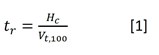
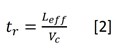
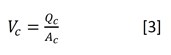
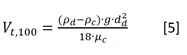
Equations [1], [2] and [3] can be combined to find terminal settling velocity corresponding to the droplet trajectory and the vessel dimensions:
eq 4
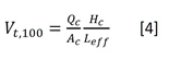
The minimum dispersed droplet sizes that would be fully separated at given flow rate can be found by substituting the terminal velocity equation [4] in appropriate settling law expression, such as Stoke’s Law:
eq 5
Where:
ρd – Density of dispersed phase.
ρc – Density of continuous phase.
g – Gravitational constant.
dd – Droplet size of dispersed phase.
µc – Dynamic viscosity of continuous phase.
Rearranging above equations, the separator dimensions can be expressed as a function of the operating and process conditions, which is known as the droplet-settling equation:
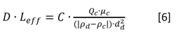
eq 6
Where:
D – Separator diameter.
– Dimensionless parameter, which is a function of gas-liquid interface level.

For an existing separator vessel, the dimensions (D, Leff) are known. Therefore, larger droplet size of the dispersed phase, due to the application of a low shear valve upstream of the separator, would enable higher production rates of the continuous phase. This is of course dependent on the downstream system being able to handle increased flow rates.

The low shear Typhoon System affects the feed stream by increasing, in comparison to standard valves, the average droplet sizes of the dispersed phase. The effect of Typhoon System on the droplet sizes can be graphically shown by plotting the droplet size distribution curves generated downstream a standard control valve and Typhoon System.
mokveld-ts-droplet%20size
Figure 3. - Droplet size distribution curves for standard control valve and Typhoon System.
Figure 3 shows the results of experiments with a North Sea crude oil. The experiments are performed with a water/oil mixture with an oil concentration of approximately 2000ppm. The relatively low oil concentration is necessary to enable online droplet size measurements. For this reason, the average droplet size of the dispersed phase is also rather small. In actual field applications, due to much higher oil concentrations, the droplet sizes in the dispersed phase are normally around two orders higher to those from the lab experiments shown here. Real time measurements of the droplet distribution in the dispersed phase downstream of the choke valve are impossible to obtain, as the phase concentrations, mainly the oil and gas, are too high. Nevertheless, the indirect effect of a low shear Typhoon System is clearly observed in both field and lab tests through the reduction of the cumulative volume (ΔV OiW) of the dispersed oil content in produced water effluent. Field installations of a Typhoon System installed upstream the separator, resulted in a 45 to 60% reduction of the OiW content measured on the separator water outlet. Realistic lab tests showed a water quality improvement between 50 and 90%.

The droplet settling equation [6] can determine the smallest size of the dispersed droplets that would be completely separated, i.e. the separator droplet cut-off size - dds. Using this droplet cut-off size together with the red droplet distribution curve from a standard choke valve (point “b” in Figure 3), enables one to calculate the dispersed oil volume in the produced water on the separator water outlet (point “a” in Figure 3). By replacing the standard choke valve with a Typhoon System, a higher droplet cut-off diameter - dds (point “c” in Figure 3) can be used in the droplet settling equation for the same volume of dispersed oil carry over to the water phase. Improvement of the droplet size with the Typhoon System is shown by the blue droplet distribution curve.

As mentioned, for choke valve applications, it is not possible to directly measure the difference in droplet size due to the high fractions of oil, gas, and water present. A certain degree of coalescence can also be expected independent on the valve type that is used. Conservatively therefore an average droplet size increase of 10% to 15% is used in this paper to evaluate the result on the separator capacity.

To quantify the effect of the larger droplets when using a low shear Typhoon System, the droplet settling equation [6] can be used. For a given vessel, the left side of the equation is constant. Therefore, the increase in cut-off droplet diameter would allow less retention time required to obtain the same water quality, i.e. the production rate can be increased. A 10 to 15% increase in the droplet cut-off size due to use of Typhoon System, will enable 21 to 32% increase in production flow rate for a constant OiW content in the water outlet.

On the other hand, if the quality of the produced water is restricting production capacity, the improvement of the water quality when using the low shear Typhoon System, compared to a conventional choke valve, is also clear using Figure 3.
Using the same droplet cut-off sizer - dds of the existing separation system together with the blue droplet distribution curve (point “d” in Figure 3) enables one the calculate the dispersed oil volume in the separator water outlet (point “e” in Figure 3). The difference in water quality compared to the standard choke valve can now be determined from Figure 3 (moving from point “a” to “e”).

More elaborate sizing models are available in the literature for the gravity separators, which may include coalescing effects in the feed pipe, flow distribution by separator’s inlet device, effect of separator internals, etc. The core of these more elaborate models, however, is still based on the droplet-settling theory. The effect of the use of low shear valves on the feed to the separator are therefore also clearly visible in these models.

TYPHOON SYSTEM APPLICABILITY TO GREEN FIELD PROJECTS

Including Typhoon System in the process plant design from the planning phase will help to optimize the separation system and prevent or significantly reduce formation of tight emulsions. Thorough evaluation of the capacity constraints can result in more compact separators necessary to satisfy the design parameters with regards to the separation efficiency required. Droplet-settling theory can be successfully applied for the sizing of the separator with regards to liquid carry over to gas phase, as well as oil and water carry over to the corresponding produced water and bulk oil streams.

For field conditions where gas-liquid ratio is expected to be low, it is fair to assume that the main three-phase separator capacity constraint would be the quality of the outlet liquid phases. Without available droplet size information, it is common to choose a recommended cut-off diameter size for separator sizing [6]. Recommendations can be found in SPE “Petroleum Engineering Handbook”. When using the same conservative assumption of the Typhoon System’s average droplet sizes increase range of 10-15% for the lower size range, the effect on the required separator size can be evaluated.

Equation [6] can be rewritten to evaluate the percentage reduction in the separator size that can be achieved by using low shear flow control technology:
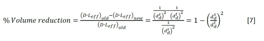
eq 7
Where:
dds – cut-off diameter generated by standard choke valve.
ddt – cut-off diameter generated by Typhoon System.
The 10 to 15% increase in dd results in a 17 to 24% reduction of the effective separator volume required.

CONCLUSION

Reduction of shear forces acting on the fluids in the gathering system upstream of separation trains by utilization of low shear flow control technology, like the Typhoon System, minimizes droplet break-up and the formation of tight emulsions, thereby improving separation and increasing separation capacity.

Implementation of Typhoon System is a simple and efficient solution for debottlenecking the liquid capacity of a three-phase gravity separator. The Typhoon System retrofit does not require any modification to the separator itself. In most of the cases, Typhoon System can simply replace existing choke or control valves.

Furthermore, Typhoon System can be used to increase the separator efficiency instead of increasing its capacity. This is particularly useful when there are problems with reduced separator efficiency due to tight emulsions. Additional benefits could be a reduced requirement for separation enhancing production chemicals like demulsifiers and reduced heating of the liquids.

Share:

logo2a

Learn more about low shear

In this section you will find some more information on different aspects of low shear. The main philosophy of low shear production is to instead of challenging the effects focus on the causes to separation problems.
Learn more about low shear

For more information contact:

niels
CEO Typhonix

NIELS VAN TEEFFELEN

niels.teeffelen@typhonix.com
mokveld logo 0
Lead Sales Engineer - Low Shear at Mokveld

Andy Little

Telephone: +44 7968 551504
Andy.little@mokveld.com