The majority of process valves can be divided into two types of applications: Isolation valves and control valves. Isolation valves have two positions of operation: Open and closed. They cause minimal or no disturbance to the flow passing through.
Control valves are designed to regulate the process specific parameters, such as flow rate, pressure drop, temperature and liquid level. Control valves resemble an orifice of some sort, which can change the opening depending on a signal from a controller. Fluid flow, passing through the restriction, experience intense turbulence and variations in pressure drop and flow velocities.
In the case when two or more immiscible liquids are present in the multiphase flow, the turbulence will stimulate the mixing. High intensity turbulence will lead to shearing of the liquid phases and the creation of an emulsion. An important characteristic of an emulsion is the droplet size distribution of the dispersed phase. The dispersed droplets vary in size and are usually spread in the range from 1 to 1000 µm. A common correlation is that the higher the mixing intensity, the greater the shearing, and the smaller the average droplet size of the dispersed phase. Emulsions can be classified as tight, medium or loose emulsions, following the increased average droplet size from smallest to largest.
Emulsions are undesired, but a commonly unavoidable phenomena during multiphase flow in a process plant. Large gravity-based separators are commonly used to separate mixed fluids into clean phases. Separation occurs by droplets from the dispersed phase travelling through the continuous phase to the phase interphase. The efficiency of gravity separators strongly depends on the droplet sizes of the dispersed phase as can be seen from Stokes’ law, describing the droplet maximum vertical (settling) velocity.

Where:
v
t Terminal velocity [m/s]
g Gravitational constant [m/s²]
d Droplet diameter [m]
ρ
c Density continuous phase [kg/m³]
ρ
d Density dispersed phase [kg/m³]
µ
c Dynamic Viscosity continuous phase [Pa·s]
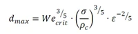
Hinze (1955) has described the shearing effect in the turbulent flow by formulating the maximum sustainable droplet size as a function of flow and fluid conditions:
Where:
d
max Maximum droplet diameter [m]
We
crit Critical Weber number [-]
σ Interfacial tension [N/m]
ε Mean energy dissipation rate per unit mass [W/kg]
We
crit determines the state at which external deforming forces acting on the droplet exceed the counter-acting interfacial tension force, which lead to droplet break-up.
The mean energy dissipation rate per unit mass, ε, is the parameter that describes the intensity of the turbulence. As the kinetic energy in the turbulent flow cascades from large scale eddies down to smaller ones, energy dissipates into heat due to viscous forces. The energy dissipation rate is the parameter used to determine the amount of energy lost by the viscous forces in the turbulent flow. In order to reduce shear forces and increase maximum droplet size of the dispersed phase, the mean energy dissipation rate must be reduced.
For the flow through a control valve ε defines as:
Where:
ΔP
perm The permanent pressure drop [Pa]
Q Flow rate [m³/s]
V
dis Volume used for energy dissipation [m³]
In a given system, the process determines flow rate, pressure and the fluid density. Therefore, the only parameter that can be used to decrease the energy dissipation rate is the volume involved in dissipating the required energy.
The definition and the purpose of the low shear valve is to reduce the shear forces acting on the fluids, while maintaining control properties. One effective way to reduce the shear forces in a control valve is to increase the volume involved in the energy dissipation.
Utilization of the hydrocyclone principle in a control valve increases the volume at which pressure drop occur. A swirl motion, similar to one that is established in the hydrocyclone, is induced in the fluid flow downstream the pressure-reducing element (globe or cage). In conventional control valves most of the pressure reduction occurs within the restriction itself. This is due to high velocity acceleration of the fluid during the flow through the restriction and following strong deceleration right after. The swirl motion in the cyclonic valve leads to maintaining the higher fluid velocities created by the flow through the restrictions. In addition, conical shape of valve’s downstream volume accelerates the fluids further in a spiral direction, thereby contributing to the pressure decrease. The cyclonic valve’s geometry utilizes the conical volume downstream the restriction in addition to the volume of restriction itself used for pressure reduction.


